The number a fitter checks first
Every socket-weld flange swallows the pipe end. isocut reads the drawing, subtracts the real take-out from ASME B16.5, and hands the saw a number that fits the first time.
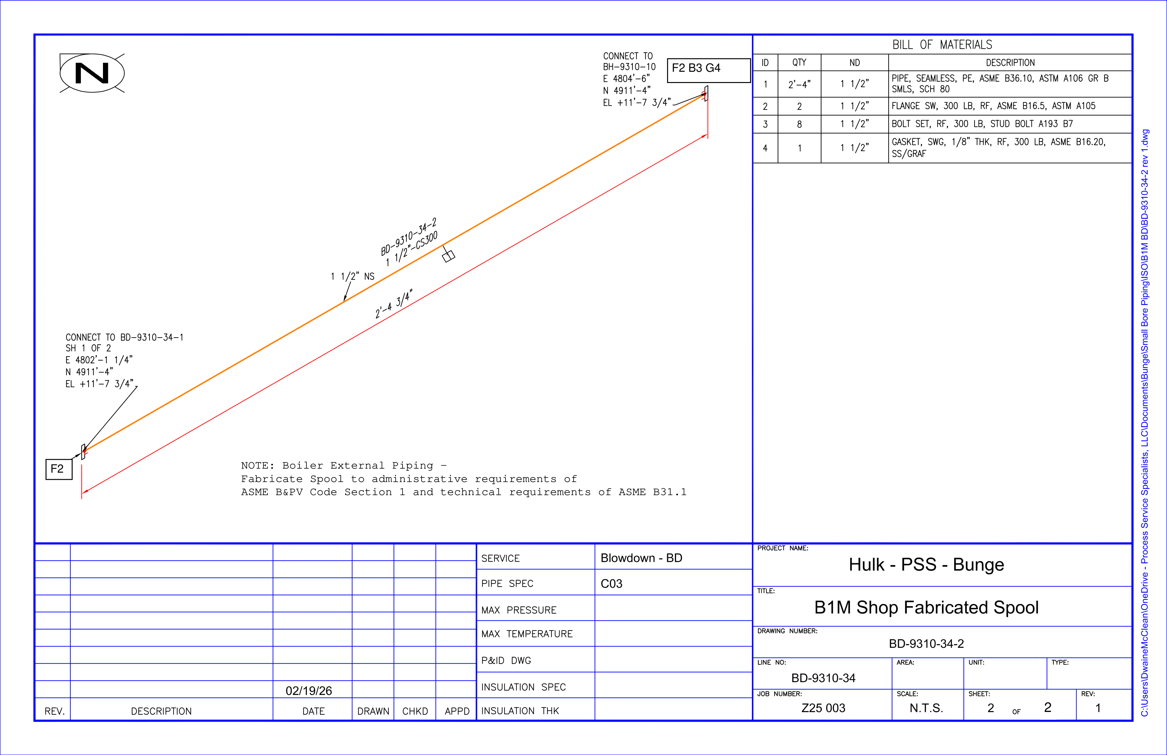
Try to Ctrl+F a cut length in this PDF and you get nothing — the dimensions and BOM are exploded to vector lines. isocut reads it visually, the way a person does, not by scraping a text layer.
It pulls the spool apart: a 1.5" run, two socket-weld flanges, the drawn dimension 2'-4 3/4", the BOM, and the end coordinates printed at each connection.
The 2'-4 3/4" is measured face-to-face between the flange faces. That is not the pipe. The pipe slides into each socket and stops short — so the steel you cut is shorter than the drawing says.
For a 1.5" 300# socket-weld flange, ASME B16.5 gives length-through-hub Y = 1.19" and socket depth D = 0.63". The pipe bottoms, then backs off 1/16". That is 5/8" gone at each end — not a guess, geometry.
2'-4 3/4" − 5/8" − 5/8" = 2'-3 1/2". And the drawing's own end coordinates measure 2'-4 3/4" apart — matching the drawn span to the fraction, so the input is verified, not trusted.
Cut list — BD-9310-34-2
| Segment | Size | Spec | End A | End B | Drawn | Take-out A | Take-out B | Cut length | Basis |
|---|---|---|---|---|---|---|---|---|---|
| BD-9310-34-2 | 1.5" | CS300 | sw_flange 1.5" 300# SW | sw_flange 1.5" 300# SW | 2'-4 3/4" | 5/8" | 5/8" | 2'-3 1/2" | drawn dim |
Upload a piping iso PDF and isocut extracts the cut list the same way. Sharpest on fabrication spools; complex multi-sheet design isos are still being tuned.